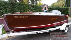
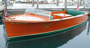
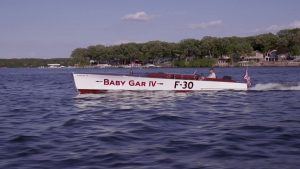
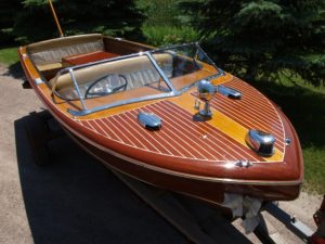
1929 / 2022 TYPHOON 30′ Modern Classic – BMW V12 – $750,000
Originally 1929 40ft long designed by George Crouch custom built for Edsel Ford.
This 8 year 4,000 hour recreation is 30ft long (completed 2022). BMW V12
$750,000 serious inquires only. All offers and trades considered.
Call Mahogany Bay for price 952-495-0007
Call Todd direct for Details 612-414-5242
Published in Wooden Boat Magazine as a Premier Project!
My experience with the building of that project left me with a want for a better challenge and therefore I decided to build a replica of the famous runabout “Typhoon” which was designed by George Crouch. The problem I had was finding any drawings for this project and upon searching the internet I found a lines drawing of Teaser. Using a magnifying glass and a digital vernier caliper I was able to copy the small drawing into Auto Cad. Below is the drawing I found and a sample of the digital drawing that resulted.
Once the lines drawing was completed I could then draw each frame and add the webbing. Below you will see the frame and the related parts. Also you can see the chassis as indicated by the blue lines.
On the digital drawing I drew in the frame offsets, engine, transmission, shaft, rudder, steering and seats. This was extremely helpful in laying out the major components in order to make sure everything would fit correctly.
After completing the drawing I then printed out the frames on a scale of 1 to 10 and glued the paper to 1/8 inch plywood. I cut the frames with a scroll saw and then used them to construct a scale model of the boat. This way I could see if my digital drawing was correct.
I then made a drawing for CNC cutting of templates for the frames. To be clear I did not CNC the frames, these were made by hand using the templates as a guide for my router. The frames were made from solid mahogany and but in order to keep it practical I cut planks from 4 x 6 inch stock and then after planning down to ¾ inch I then glued the parts together. This way I could have very wide frame parts without having to purchase large planks and ending up with a lot of waisted material. In the photo below you will see the planks glued together and the finished product. One thing I learnt about cutting frames is that as you remove material the wood will take another form as it gets unstressed. Therefore the trick is to lay the template over the frame to be cut and then trace about 3mm around the template. First cut the frame along the marked line to remove the excess and then the frame will be relieved of stress. After it is trimmed you can then staple the CNC machined template over the frame for guiding the router.
I had a master drawing that was printed out glued to a wood panel. This allowed me to secure the frame sections to it during the assembly process to make sure they were aligned exactly as intended. As you can see in the image below the radius between the bottom and side member has not be cut. This was done after the parts were glued together and the gusset was added. The gusset became the guide for the router so that there is a perfect match. The gusset is mahogany plywood and there are no screws so that the assembly has a nice clean look.
The finished frames were then set up on an aluminum Chassis. The reason I used aluminum was to make sure that the structure was strong and that there would be no chance of warping due to humidity. Each frame had a centerline marked into it before it was finished with two coats of epoxy. Then I used a piano wire stretched tightly from the front of the chassis to the rear in order to get perfect alignment of each frame. The aluminum chassis had welded supports with holes for each frame and once the frames were aligned I only had to drill holes in the wood and bolt them on. Also by using the tube frame I was able to hide cables and hoses inside in order to make a nice and clean installation.
As you can see by the photos above and below my garage is not very wide. Therefore I made 5 wood runners that extended from side to side transverse over the floor. These were leveled and an edge was added so that the 10 dollies wood not roll off. This way I could slide the building jig from side to side in the garage which left me about 2 feet of space to work on either side. You can see the dollies on the left photo below.
I used European Oak for the longitudinal battens and everything is glued together with epoxy. The hull side is done with cold mould construction but instead of beginning with a 45 degree angle on the first layer I used a panel of okuome marine plywood that extended from frame to frame. I used a cardboard template to copy the required size to the panel so there would be no mistake. The mahogany veneer panels were very expensive and therefore any mistake would mean that a 2 x 3 foot piece would be wasted. The joint between panels is at each frame so that you cannot see it from the inside but remains strongly secured. By using trucking straps I was able to pull the panels tight to the frames and longitudinal battens during the gluing process.
When you look any where on the inside of the hull you will see a beautiful wood finish. Everything was coated with two 2 layers of epoxy and then varnished.
The first layer of bottom planking was glued to the frames and battens by using staples with shipping straps. The straps helped prevent the staple from digging too much into the wood and also made it easy to remove them after the epoxy was dry. The stable dents were filled with a mixture of epoxy and sawdust. Due to the fact that the bottom is very flat I decided to use a vacuum bag system to pull the bottom panels tight to the first layer. The bow was more complex and therefore I used 4 inch cold mould strips at 45 degree angle for the first. After the first layer I once again used a still vacuum bag. The bottom is planked with four layers of 4mm marine plywood of which the last three layers were applied with vacuum.
The hull sides were finished with 1/8 inch solid mahogany veneer. This was necessary because of the rounded shape (there is virtually nothing straight on the whole side). Any thicker veneer would not be flexible enough to match the rounded hull form. Again I used trucking straps and self made adjustable wood clamps together with long battens to press each plank onto the hull. In the photo on the right below you can see the upper part of the top plank is very uneven but the lower part is tight to the other plank.
One important detail about the hull planking is that this was not done by cutting each plank to a 4 inch width as would normally be done. That method leaves the seams between panels going the direction that the frame form will dictate. Instead I wanted the planks to be parallel to the water line. In order to do this I had to make the first plank perfectly straight before the next one could be added. Therefore I glued one horizontal layer of 5“ oversize planks from bow to stern and then machined it straight by using a guide strip that my router could follow for the full length. The next plank would be machined on one edge to be perfectly straight. Then I had to clamp the plank to the hull side as close to the first plank as possible by using wedges, battens and shipping straps. Being that the first plank has a form that matches the hull side there were gaps at each end. These gaps were measured and recorded every 12 inches along the length. Then the plank was removed from the hull side and laid on a cutting table. The cutting table had clamps that allowed me to fix a batten over the plank that would be used as a guide for my router. Then I would use a vernier caliper to offset the batten from the straight edge to match the record measurement taken when the plank was fit to the hull side. This was then machined away and then I made a test fit on the hull side once again pulling it in place with the clamps. In most cases the plank fit perfectly. Also you had to trust the digital information, it was very accurate and you had to press it tight to the adjacent plank to realise it was correct. This plank would then be glued to the hull side and then the next plank could be added. This process took six months or about 350 hours.
After finishing the hull planking I then added red stain and then coated everything with 6 layers Epifanes PP. The hull bottom was laminated with two layers of fiberglass cloth up to the water line. Then two layers of epoxy barrier coat was applied before two layers of antifouling was added.
After the deck battens were installed I then glued two layers of 4mm okuome marine plywood. The first layer had mahogany veneer on one side so that when you look up from the inside it also was nicely finished. The deck planks were made with 3/16 inch strips of Mahogany 1 13/16 inch wide. Between each plank is a 5/32 inch wide strip of Maple. Before any deck planks can be installed a maple strip was installed on the full length of the boat at mahogany hull side plank. Then the center plank for the full length of the boat is installed. Once that is dry I then install a maple strip and a mahogany plank by clamping it down from the ceiling of my garage. The Maple strip is about 1mm proud of the mahogany plank and that gets sanded back once the deck is compete. The planks and strips were added one row at a time from bow to stern before starting the next row. The reason for this is that the planks are color matched so that the color remains for the full length.
It was necessary to apply the stain and varnish to the hull side because it would not be possible to do this after the maple strip was added. The maple strip would have also been stained and therefore the hull side had to be completely ready before the deck started. It was a little tricky sanding the Maple strip that was adjacent to the already stained and varnished hull side. I used a razor blade as a scrapper to make sure I did not cut into the varnish or the stain. If the stain was removed it was very hard to get the right color match and therefore it was necessary to take your time. When the deck was finished I coated with 6 layers of Epifanes PP varnish. Then the hull and deck were coated with 8 coats of Epifanes clear varnish with UV protection. The deck mahogany planks were left in there natural color.
Once I competed the hull and deck I started the technical installations. The engine is a V12 BMW 5.0 liter M70 unit that I removed from a 750i. I marinized by using a Yanmar intercooler and self made water cooled exhaust manifolds. The original electronics system has been installed in a mahogany box with two ventilation fans. There are two batteries installed and a battery switch is used. The engine electronic system is powered continually from the port battery so that the memory stays active. The original diagnosis plug is reused. Stainless steel pipes were fabricated for the cooling water system so that only short hoses are used. The gearbox is a Borg Warner Velvet Drive 1 to 1 ratio with water cooling. A special adapter was machined to mate the BMW flywheel to the Velvet drive flex plate. The bellhousing from the BMW automatic transmission was machined to fit the flange of the gearbox.
Fabrication of the transmission mounts and engine mounts was relatively easy. First I made a paper drawing and glued it to a wood template. The drawing had the crankshaft line and keel plank on it so that I could drill a ¼ inch hole through the keel at the correct angle. Then I used a hole saw to drill a 1 ½ inch hole for the shaft tube. I made a shaft tube that is flanged to a frame and protrudes inboard enough for support of the PSS shaft seal. I installed the propeller shaft and then supported it in the middle of the shaft tube. Then I made the shaft strut by welding a tube to a 12mm thick plate that was hand formed to a tear drop shape. The shaft bearing was then installed into the tube. I had a T frame and roller system bolted to the garage ceiling beams and this track allowed me to pick up the gearbox behind the boat with a chain block so I could easily roll it over the engine bay. While it was hanging in the chain block I bolted it to the shaft flange. This kept the gearbox in perfect alignment. Then I installed supports for the Volvo IPS 600 mounts and installed them. I fabricated plates that bolted to the gearbox and then I made horizontal strips that fit the vibration mount bolt. The horizonal strips were tack welded to the side plates and then removed from the boat for finish welding. The transmission was then removed from the boat and connected to the engine. Then with the same roller system I hung the engine and transmission in the engine bay. The welded transmission mounts were installed on the transmission and the shaft was reconnected. This put the engine in perfect alignment with the shaft. Then I fabricated the engine mounts in the same manner as the transmission mounts.
The propeller is located aft of the transom step and therefore I was afraid of cavitation. Therefore I made an anti cavitation plate that prevents the propeller from drawing air from the surface.
The steering box is from a BMW 750i and mounted to a solid plate under the dash board. The original lever is connected to a shaft that has a lever on each end. This transmits the steering lever movement to a steering rod that uses rod ends to account for any flex. The steering rod is connected to the aluminum chassis and extends to the aft rudder compartment. The fore and at movement of the steering rod is changed to a turning force by a series of shafts and levers. The rudder angle is 35 degrees in both directions.
The balanced rudder is welded to a 1 1/4 inch shaft which extends to all the way to the deck. A shaft tube with a welded flange has been installed in the hull bottom. This shaft tube extends to 4 inches above water line so that it is impossible to leak water under any circumstance. Before the rudder shaft was welded to the rudder I machined two groves into is so that O ring seals could be used instead of a rope packing. Custom made rudder bearings support the shaft at the bottom and the top of the shaft. The upper bracket is bolted to the deck frame for a very solid support. A large ring is bolted to the top of the shaft and this rests on the bearing to give the shaft axial support so it can never fall out. The steering lever was hand made to clamp onto the rudder shaft.
The fuel tank is made from two plates of 5/32 stainless steel that were specially bent so that there were minimum welds. The tee shape that fits under the aft cockpit seat and has a capacity of 25 gallons. Two BMW electric pumps and a tank level sender are installed on the man holes that is bolted to the tank top.
I purchase an industrial sewing machine so I could fabricate the Leather seats. The leather material with an offset of 5 ½ inches was sewn to backing material that had 4 inch offsets. This made pockets for ¾ inch foam so that the pleats would be very deep and hide the stitching. I wrapped the foam in plastic and then pulled it into the pocket with vice grips and a wire. After that the leather covers were stapled to a wood base plate that had 3 inches of foam.
The steering wheel was made from a laser cut stainless steel rim with four spokes. The rim was then covered with laminated half round circles of mahogany. The classic instruments are installed in a panel that is covered with machine turned surface. On the dash panel you will find the switches for the navigation lights, search light, blowers and horn. On the starboard side of the steering column you will find the key switch and push button start. The transmission is shifted by a floor mounted lever with a spring loaded lock mechanism. There are levers and push rods that transmit the lever action to the gearbox. Normally boats of this era would use a steering column mounted fuel control but that is not possible with a modern steering box and therefore I used a foot gas pedal.
The bow and stern cleats have an integrated eye that is used for lifting. Each cleat is connected to a turnbuckle that in turn is connected to the keel in the bow and the aluminum frame at the stern. The bow and stern cut water pieces were laser cut and then welded together.
The window frames are hand made from 316L stainless steel. They can be disassembled in case a glass panel needs to be replaced. The glass is 6mm thick.
The step plates have been cnc machined with the name Typhoon engraved.
Behind the second set of seats there is a pocket that can be used for the storage of the convertible top. There are four hatches that fit with almost invisible gap. The convertible top is in progress and hopefully will be finished this winter. After that a cover will be made for the entire boat.
The entire interior can be removed if necessary in order to access the bilge area. Nothing is glued and therefore it can be removed by taking out some screws.
I saved the original V12 emblems and installed them as is with the original patina.

I installed a Fusion marine stereo system but the speakers, radio and amplifier are installed out of sight so that they do not look out of place.
$750,000 serious inquires only. All offers and trades considered.
Call Todd direct for Details 612-414-5242
Mahogany Bay Main 952-495-0007


